ESC protocols overview with implementation on STM32
What is ESC protocol?
When our flight controller calculates new values for each of the motors they need to be sent to ESC microcontroller which can then process these values and control MOSFETs. How exactly signals are received and then send to motors is ESC's software secret, which is another really interesting and complicated topic. For now, let's know that we can not control the motors or even MOSFETs from our FC, we need to send new values between two microcontrollers. And here is our topic: how to exchange this information efficiently and correctly?
Analog way
The oldest and probably the most recognizable protocol is PWM signal, taken from servo controlling. All the analog protocols are based on this signal. Period and duty cycle changes, but the idea remains the same: the FC sends a signal, and the ESC measures the time of the high and low signal, and this measured value is treated as a new set for the motor. The main features of this approach are:
- simplicity of implementation
- low load on the transmitting and receiving device
- sensitivity to interference
- required calibration
Traditional PWM
The standard PWM signal used in servos has a period of 20 [ms] and a duty cycle of 1 - 2 [ms]. This gives a refresh rate of 50 [Hz]. For servos, this value is quite sufficient. Also, ground vehicles, aircraft, helicopters or submarines often use a refresh rate of 50 [Hz]. Multi-rotorcraft definitely need higher frequencies for proper operation, but ESC would work with this signal perfectly fine. You can test it and connect a traditional PWM radio receiver directly to ESC and test if the motors would spin (please do it without props on).

Modification of PWM
The first and obvious improvement of the above signal can be increasing frequency. Since we use only 1-2 [ms] for the duty cycle we can send new values close to 500 [Hz] (for real applications 490 [Hz]). This solution was the gold standard for a long time and allows for pretty good quadcopter steering. The next simple improvement of this protocol is increasing the resolution. Instead of 1000 steps for 1 [µs] we can use 2000 steps for 0.5 [µs]. We can make it even more precise but it has an impact only if ESC will sample our signal with a high enough resolution.

OneShot125 and OneShot42
A significant limitation of the above PWM signal is the duration of the duty cycle (1 - 2 [ms]). This not only limits the maximal frequency of the protocol but also introduces a delay that negatively affects the control of the entire drone. When new values are calculated ESC has to wait a duty-cycle time before can process measured values and steer motors. To improve this the OneShot125 and OneShot42 protocols reduce the duty cycle 8 times and 24 times accordingly. It gives 125-250 [µs] (OneShot125) and approx. 42 - 84 [µs] (OneShot42). This increases the maximum possible main loop frequency to 4 [kH z] or 12 [kHz].
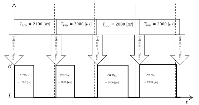
OneShot also solves another problem arising from the lack of synchronization of the main loop and PWM signal generator. In an ideal situation after determining the correction in the main loop, the new motor values are sent to the ESC. In reality, there may be some delays in the PID loop and the update of the PWM duty cycle can occur a bit later. Normally the PWM signal starts with a fixed period and the new values that were calculated slightly later will be taken into account only in the next loop (the previous values of the settings are repeated and only after they are transmitted new ones will be sent). In this way, a delay is added, which will only increase until the PWM period is exceeded (then it will start accumulating again). Therefore, the maximum time from the moment the new corrections are determined until the signal is received by the ESC is $2∗T_{PWM}$.
 |
| Ideal situation |
 |
| Real situation |
To prevent this in the OneShot protocol, after the signal is transmitted, PWM generation stops. It is resumed only when the main loop sends new correction values. In this way, the delay is only the duration of the signal frame (125 -250 or 42-84 [µs]). We lose averaging effect of sending the same value to the ESCa a few times but it is not a big deal - more about it later. Anyway, OneShot125 is one of the most widely used analog protocols for now.
 |
| OneShot example |
MultiShot
MultiShot is 10 times faster than the OneShot125. In addition, the range of the signal change from a minimum of 5 [µs] to a maximum of 25 [µs] (range 20 [µs]). The remaining operation is analogous to the OneShot protocol. Due to the very short duration of the signal in this protocol, not all ESCs support it.
Digital way
Analog protocols have several major drawbacks. The desire to eliminate them, motivated to create a new protocol. The main motivations:
- reduce susceptibility to interference,
- lack of need for calibration,
- desire to send other messages than just motor setpoints.
Since it was necessary to use the same hardware for transmission (PWM used before), a solution known from addressable LEDs was adopted.
Dshot 150/300/600/1200
This solution is based on the usage of 2 different PWM fill as 0 and 1-bit values. The PWM signals sent in succession are received as 0 or 1 bits. There are 11 bits of motor value, 1 bit for the telemetry flag and 4 bits of CRC. In this order, the DShot frame is transmitted after which a reset signal is required - low signal for 2 bit's time. Then it can be decoded and if CRC check is valid it is used for motor control. The below diagrams show the construction of 0 and 1-bit:
 |
| 0-bit |
 |
| 1-bit |

As you probably guessed number 150, 300, 600 or 1200 corresponds with bits per second sent with these protocols. We know how each bit is constructed and the number of bits in the frame so we know the timing of the DShot protocol. In the table, the durations of the frame are presented for each version. As you can see these timings are not much superior to analog protocols but it is not the most important thing. Since the value is digital there is no room for measurement inaccuracies and if some bits are not transmitted correctly the whole frame is discarded. Of course, there is no need for calibration also.
| protocol | T0H [µs] | T1H [µs] | bit [µs] | frame [µs] |
|---|---|---|---|---|
| DShot150 | 2.5 | 5 | 6.67 | 106.72* |
| DShot300 | 1.25 | 2.5 | 3.33 | 53.28* |
| DShot600 | 0.625 | 1.25 | 1.67 | 26.72* |
| DShot1200 | 0.313 | 0.625 | 0.83 | 13.28* |
| *it is necessary to add 2 bits of reset | ||||
After transmission low signal has to be set for at least 2 bits period for ESC to reset. The first 11 bits give a range of values 0-2047 possible to send to ESC. 0 value is reserved for arming motors (after powerup this has to be sent to ESC). 1-47 values give some control over ESC but depend on the software on ESC. 48-2047 is the range of motor value so there are 2000 steps for controlling its speed. Most of the modern ESC regulators have a UART output, through which it can send data from sensors (temperature, current measurement etc.). In order for this data to be sent, the ESC must receive a request from the FC. This is done by bit 12 in the DShot frame, if it is set high the data telemetry data will be sent. The last 4 bits are the checksum. The way CRC is calculated and a much more detailed explanation of this protocol you can find here.
BDShot
This protocol allows for communication in both directions FC<->ESC. It is very similar to DShot but the signal itself is inverted (the high parts of DShot are low in BDShot). This gives real-time access to RPM of each motor which is great for filtering noise from sensors and allows for great flight improvement. Unfortunately, this feature is a bit heavy on the processor and some ESC can't handle it. More about implementing this feature in the next post.

After transmission, ESC will wait a bit (20-35 [µs]) and will start sending the eRPM value which allows calculating the real motor RMP value. It is not so simple to receive this value but more about it in the next post.
Frequency, resolution, delays
Basically, we can say: higher frequency gives smaller delays and with the higher resolution allows for better control of the quad. Let's try to dive a bit deeper and understand what really matters for better flight performance.
Let's understand the resolution problems. For STM you have to set up a PWM clock prescaler which defines the smallest time step which is counted by the counter. Basically, this way you defined your signal resolution and for the step of 1 [µs] it gives 1000 values between 1-2 [ms]. Lower prescaler and you will have 2000 steps or even 8000 for 1 [ms]. But regardless of the sent signal resolution signal received by the ESC will have a resolution with which will be sampled by ESC. This can differ from ESC software but unfortunately, it usually is 1000 steps. In that case, your high-resolution signal sent from FC will not introduce any benefit. Digital protocols give a fixed resolution of 2000 steps (48-2047). For convenience in my code, I use always 2000 steps for both analog and digital to keep the main loop the same for all protocols (there are no drawbacks to sending signals with higher resolution to ESC with analog protocols).
When it comes to the frequency we need to understand that our quadcopter can not react immediately (inertia of motors and a whole quad). So there is some max frequency above which our commands will have no effect before the next commands come. The lighter the drone, the higher this frequency is. For a 5-inch quad, it probably will be about 1-3 [kHz]. If so, what's the point of the 4, 8 or even 12 [kHz] frequency for protocols such as OneShot?
The first advantage of a shorter duty cycle is a smaller delay between new values calculation (by FC) and applying them to the motors (by ESC). And this is true even if you use those protocols with lower frequencies than their max.
Moreover, there is a benefit of sending the same values to motors more often than they can react when we use analog protocols. Since the measurements of send values can vary, new values sent to the motors can be not exactly what we sent from FC. However, if we will send those values a few times the value measured by ESC (so the value sent to the motors) will fluctuate around desired sent from FC. Since motors can't react to each new value they will act like averaging filters and an outcome will be closer to the desired value. This is true for analog protocol but irrelevant for digital since there is no fluctuation of the received signal. But regardless of the protocol type, this averaging effect will work for new values sent to ESC and may be the reason why we want to use a higher PID loop even if motors can't react for 4 [kHz] changes sent from FC.
In the end the delays. Imagine that your copter is upside down and falling to the ground. You move your sticks new desired movement is sent to the copter and received by software. Next, data are processed and motors values are calculated. They started to be transmitted and after some time (protocol frame) are taken by ESC to calculate PWM to control MOSFETs. And only now the engines can start changing their rotational speed to save your drone from crashing. As you can imagine if the time between the change of position and applying corrections will be too long drone will crash or at least fly poorly. That's why on each part of the steering quadcopter we want to reduce the time it takes. It's worth noting that analog protocols' delays vary between the min. and max. value sent by them when digital frames always last the same.
 |
| maximal time of frame |
| protocol | min. signal length [µs] | max. signal length [µs] | max. frequency [Hz] | recommended max. frequency [Hz] |
|---|---|---|---|---|
| servo PWM | 1000 | 2000 | 50 | 50 |
| faster PWM | 1000 | 2000 | 500 | 490 |
| OneShot125 | 125 | 250 | 4000 | 3900 |
| OneShot42 | 42 | 84 | 12000 | 11900 |
| MultiShot | 5 | 25 | 32000 | 31900 |
| DShot150 | 106.7 | 106.7 | 8000* | 4000 |
| DShot300 | 53.3 | 53.3 | 16000* | 8000 |
| DShot600 | 26.7 | 26.7 | 33000* | 16000 |
| DShot1200 | 13.3 | 13.3 | 66000* | 32000 |
| *with 2 bits of reset (recommended more bits for reset) | ||||
Implementation on STM
Implementation of the analog protocols is really simple since STM timers give us PWM generators with which we define a period of a signal and can decide about the duty cycle. We will change it on the fly after calculating new values in the main loop. For OneShot, we also set up PWM for generating only one period (one pulse mode). Let's see the setup function for PWM:
#define FREQUENCY_ESC_UPDATE 490	//	frequency of ESC updating
void setup_PWM()
{	//	Enable GPIOA clock:
	RCC->AHB1ENR |= RCC_AHB1ENR_GPIOAEN;
	//	Setup GPIO pins AF mode:
	GPIOA->MODER &= ~GPIO_MODER_MODER2;
	GPIOA->MODER |= GPIO_MODER_MODER2_1;
	GPIOA->MODER &= ~GPIO_MODER_MODER3;
	GPIOA->MODER |= GPIO_MODER_MODER3_1;
	//	Set alternate functions:
	GPIOA->AFR[0] &= ~0x0000FF00;
	GPIOA->AFR[0] |= 0x00001100;	// TIM2 channel 3 and channel 4
	//	Set speed (11 - max speed):
	GPIOA->OSPEEDR |= (GPIO_OSPEEDER_OSPEEDR2 |GPIO_OSPEEDER_OSPEEDR3};

	//	Enable TIM2 clock:
	RCC->APB1ENR |= RCC_APB1ENR_TIM2EN;
	//	Register is buffered (any changes will affect the next period):
	TIM2->CR1 |= TIM_CR1_ARPE;
	//	PWM mode 1 and output compare 3, preload enable:
	TIM2->CCMR2 |= TIM_CCMR2_OC3M_1 | TIM_CCMR2_OC3M_2 | TIM_CCMR2_OC3PE;
	//	PWM mode 1 and output compare 4, preload enable:
	TIM2->CCMR2 |= TIM_CCMR2_OC4M_1 | TIM_CCMR2_OC4M_2 | TIM_CCMR2_OC4PE;
	//	channel's polarity -> when channels are active (for PWM 1 mode when CNT<CCR) signal is high:
	TIM2->CCER &= ~TIM_CCER_CC3P;
	TIM2->CCER &= ~TIM_CCER_CC4P;
	//	Channel 3 enable:
	TIM2->CCER |= TIM_CCER_CC3E;
	//	Channel 4 enable:
	TIM2->CCER |= TIM_CCER_CC4E;
	//	Counter counts every 0.5 [us] (typically 1 step is 1 [us]).
	//	For better resolution and easier Dshot implementation it is 0.5[us].
	//	Notice that lowest motor_value (2000) is still 1[ms] long as in typical PWM):
	TIM2->PSC = 84/2 - 1;	// TIM2 source clock is 84 [MHz]
	TIM2->ARR = 2000000 / FREQUENCY_ESC_UPDATE - 1; // 1 period of PWM
	TIM2->CCR3 = 2000; // PWM length channel 3 (1 [ms])
	TIM2->CCR4 = 2000; // PWM length channel 4 (1 [ms])
	//	TIM2 enabling:
	TIM2->EGR |= TIM_EGR_UG;
	TIM2->CR1 |= TIM_CR1_CEN;
 }
The above setup is only for 2 motors connected to TIM2 but the code for different timers is the same (check which GPIO pins connect to which timers channels' outputs). Now when you want to change the PWM duty cycle (probably after the main loop) you write:
 void update_motors()
 {	//	motors values are in range 2000-4000:
 	TIM2->CCR4 = motor_1_value; // value motor 1
	TIM3->CCR3 = motor_2_value; // value motor 2
	TIM3->CCR4 = motor_3_value; // value motor 3
	TIM2->CCR3 = motor_4_value; // value motor 4
 }
OneShot125 setup is quite different. We want one pulse of PWM so let's activate One Pulse Mode for the timer. However, we can not generate a high signal for duty-cycle and then low (STM after overflow will go back to high). One Pulse mode allows for generating delay and then PWM signal (with length calculated based on ARR and CCR values). So maybe we can generate a part of desired PWM frame which stays low? (for 250 [us] PWM it would be 0 and for 100 [us] duty cycle - 150 [us]). Unfortunately, the delay can not be 0 and to be safe let's use 1 [us]. Now our frame length is 251 [us] and we set (in CCR) how long it will stay low (after this time it will go high and after overflow back to low). ESC has to wait until the end of each frame (not the best but it is max 126 [us] additional delay so better than a whole frame).
void setup_OneShot125()
{	//	Enable GPIOA clock:
	RCC->AHB1ENR |= RCC_AHB1ENR_GPIOAEN;
	//	Setup GPIO pins AF mode:
	GPIOA->MODER &= ~GPIO_MODER_MODER2;
	GPIOA->MODER |= GPIO_MODER_MODER2_1;
	GPIOA->MODER &= ~GPIO_MODER_MODER3;
	GPIOA->MODER |= GPIO_MODER_MODER3_1;
	//	Set alternate functions:
	GPIOA->AFR[0] &= ~0x0000FF00;
	GPIOA->AFR[0] |= 0x00001100;	// TIM2 channel 3 and channel 4
	//	Set speed (11 - max speed):
	GPIOA->OSPEEDR |= (GPIO_OSPEEDER_OSPEEDR2 |GPIO_OSPEEDER_OSPEEDR3};

	//	Enable TIM2 clock:
	RCC->APB1ENR |= RCC_APB1ENR_TIM2EN;
	TIM2->CR1 |= TIM_CR1_OPM; //	ONE_PULSE_MODE
	//	PWM 1 mode channel 3:
	TIM2->CCMR2 |= TIM_CCMR2_OC3M_1 | TIM_CCMR2_OC3M_2;
	//	PWM 1 mode channel 4:
	TIM2->CCMR2 |= TIM_CCMR2_OC4M_1 | TIM_CCMR2_OC4M_2;
	//	Channel's polarity -> when channels are active (for PWM 1 mode when CNT<CCR) signal is low:
	TIM2->CCER |= TIM_CCER_CC3P;
	TIM2->CCER |= TIM_CCER_CC4P;
	//	Channel 3 output enable:
	TIM2->CCER |= TIM_CCER_CC3E;
	//	Channel 4 output enable:
	TIM2->CCER |= TIM_CCER_CC4E;
	//	OneShot is 8x faster regular PWM.
	//	1 step is 1/16 [us] (normally 1 [us]):
	TIM2->PSC = 84 / 16 - 1;
	TIM2->ARR = 3999 + 16;	//	PWM frame length (250+1 [us]) cause min delay required in pulse mode
	TIM2->CCR3 = 4015 - 2000 + 1;	//	PWM duration channel 3 (125 [us])
	TIM2->CCR4 = 4015 - 2000 + 1;	//	PWM duration channel 4 (125 [us])
	//	TIM2 enabling:
	TIM2->EGR |= TIM_EGR_UG;
	TIM2->CR1 |= TIM_CR1_CEN;
 }
void update_motors()
 {	//	Motors values are in range 2000-4000:
 	TIM2->CCR4 = 4015 - motor_1_value + 1; // value motor 1
	TIM3->CCR3 = 4015 - motor_2_value + 1; // value motor 2
	TIM3->CCR4 = 4015 - motor_3_value + 1; // value motor 3
	TIM2->CCR3 = 4015 - motor_4_value + 1; // value motor 4
 	//	Reload and start timers:
	TIM2->EGR |= TIM_EGR_UG;
	TIM3->EGR |= TIM_EGR_UG;
	TIM2->CR1 |= TIM_CR1_CEN;
	TIM3->CR1 |= TIM_CR1_CEN;
 }
Digital protocols are a bit more sophisticated. We need to generate for each frame 16 bits which can have 2 possible lengths of high signal and 2 bits of low signal for reset. To do this efficiently DMA usage is required. We will make a table of 18 values for the duty cycle of each bit (16 bits of frame and 2 bits of reset). DMA will transfer these values into the timer register after each overflow (which will generate a request). Also before sending the motor value we need to calculate CRC and add it to the end of the frame after the telemetry bit. Let's start with the setup:
#define DSHOT_MODE 300 // 150/300/600/1200
#define DSHOT_BUFFER_LENGTH 18 // 16 bits of Dshot and 2 for clearing
#define DSHOT_PWM_FRAME_LENGTH 35 // number of steps for each bit
#define DSHOT_1_LENGTH 26 // number of steps for high signal for 1-bit
#define DSHOT_0_LENGTH 13 // number of steps for high signal for 0-bit

void setup_Dshot()
{	//	Enable GPIOA clock:
	RCC->AHB1ENR |= RCC_AHB1ENR_GPIOAEN;
	//	Setup GPIO pin AF mode:
	GPIOA->MODER &= ~GPIO_MODER_MODER3;
	GPIOA->MODER |= GPIO_MODER_MODER3_1;
	//	Set alternate functions:
	GPIOA->AFR[0] &= ~0x0000F000;
	GPIOA->AFR[0] |= 0x00001000;	// TIM2 channel 4
	//	Set speed (11 - max speed):
	GPIOA->OSPEEDR |= GPIO_OSPEEDER_OSPEEDR3;

	//	Enable TIM2 clock:
	RCC->APB1ENR |= RCC_APB1ENR_TIM2EN;
	//	Register is buffered and only overflow generate interrupt:
	TIM2->CR1 |= TIM_CR1_ARPE | TIM_CR1_URS;
	//	PWM mode 1 and output compare 4 preload enable:
	TIM2->CCMR2 |= TIM_CCMR2_OC4M_1 | TIM_CCMR2_OC4M_2 | TIM_CCMR2_OC4PE;
	//	TIM2 is 84 [MHz]:
	TIM2->PSC = 84000 / DSHOT_MODE / DSHOT_PWM_FRAME_LENGTH - 1;
	TIM2->ARR = DSHOT_PWM_FRAME_LENGTH - 1;
	TIM2->DIER |= TIM_DIER_CC3DE | TIM_DIER_CC4DE; // DMA request enable for 4th channel
	TIM2->CCR4 = 10; // PWM duration channel 4
	//	Channel 4 output enable:
	TIM2->CCER |= TIM_CCER_CC4E;
	//	TIM2 enabling:
	TIM2->EGR |= TIM_EGR_UG;
	TIM2->CR1 |= TIM_CR1_CEN;

	//	DMA setup:
	RCC->AHB1ENR |= RCC_AHB1ENR_DMA1EN;
	//	Motor 1:
	DMA1_Stream6->CR |= DMA_SxCR_CHSEL_0 | DMA_SxCR_CHSEL_1 // DMA channel selection
		| DMA_SxCR_MSIZE_1 | DMA_SxCR_PSIZE_1 | DMA_SxCR_MINC // memory data size, peripheral data size (size of register can vary between timers), memory increment
		| DMA_SxCR_DIR_0 | DMA_SxCR_TCIE | DMA_SxCR_PL_0; // memory->peripheral, TC interrupt, priority set
	//	Clear flag:
	DMA1->HIFCR |= DMA_HIFCR_CTCIF6;

	//	NVIC setup:
	NVIC_EnableIRQ(DMA1_Stream6_IRQn);
 }
For other motors, the setup is pretty similar but there is one important difference. Some timers have 32-bit registers and some 16-bit. When you transfer 16-bit data to a 16-bit register DMA works as expected the same for 32-bit peripheral from 32-bit memory (remember to set the correct size in DMA setup). But when you want to send to a 32-bit register from a 16-bit memory DMA will send 2 following packages to the register (to fill 32-register). So you want to trick DMA and say that register is also 16-bit and sending 16 bits to it should be flawless? NO, for some STM (F2/F4/F7) when you perform 16-bit access to a 32-bit register data will be doubled (check AHB/APB bridges (APB) chapter in RM). So you have to use memory the same size as you register*. Now we need to prepare our DShot buffer and start DMA transmission:
* You could use bigger memory e.g. 32-bit memory for a 16-bit register (you set both 32-bit sizes in DMA config). FOR TIMERS CCR registers are always 32-bit long and for 16-bit timers upper half is reserved (you will try to write to this part but it is read-only so it will be discarded). But in my opinion, it is a bad idea to try writing somewhere you shouldn't. Be cautious for other registers which can be truly 16-bit and writing 32-bit data will overwrite the next register. I prefer matching data size with peripheral size.
uint32_t dshot_buffer_1[DSHOT_BUFFER_LENGTH];	// for TIM3 it has to be uint16_t
void update_motors(timeUs_t current_time)
{	//	Prepare the buffer:
	fill_Dshot_buffer(prepare_Dshot_package(motor_1_value), dshot_buffer_1);
	//	Setup DMA:
	DMA1_Stream6->PAR = (uint32_t)(&(TIM2->CCR4));
	DMA1_Stream6->M0AR = (uint32_t)(dshot_buffer_1);
	DMA1_Stream6->NDTR = DSHOT_BUFFER_LENGTH;
	//	Start the transmission:
	DMA1_Stream1->CR |= DMA_SxCR_EN;
 }

 void fill_Dshot_buffer(uint16_t m1_value, uint32_t *buffer) // for TIM3 pointer should be uint16_t*
 {
 	for (uint8_t i = 2; i < DSHOT_BUFFER_LENGTH; i++)
	{
		if ((1 << (i - 2)) & m1_value)
			buffer[DSHOT_BUFFER_LENGTH - 1 - i] = DSHOT_1_LENGTH;
		else
			buffer[DSHOT_BUFFER_LENGTH - 1 - i] = DSHOT_0_LENGTH;
	}
	// Make 0 pulse after Dshot frame:
	buffer[DSHOT_BUFFER_LENGTH - 1] = 0;
	buffer[DSHOT_BUFFER_LENGTH - 2] = 0;
 }

 uint16_t prepare_Dshot_package(uint16_t value)
 {	// Value is in range of 2000-4000 so it needs to be transformed into Dshot range (48-2047)
	value -= 1953;
	if (value > 0 && value < 48)
		value = 48;
	return ((value << 5) | calculate_Dshot_checksum(value));
 }

 uint16_t calculate_Dshot_checksum(uint16_t value)
 {	// 12th bit for telemetry on/off (1/0):
	value = value << 1;
	return (value ^ (value >> 4) ^ (value >> 8)) & 0x0F;
 }
One last thing is the DMA interrupt code after the completion of transmission:
 void DMA1_Stream6_IRQHandler(void)
 {
	if (DMA1->HISR & DMA_HISR_TCIF6)
		DMA1->HIFCR |= DMA_HIFCR_CTCIF6;
 }
And that's it! Basic implementation of PWM, OneShot and DShot protocols. In the next post, I will describe BDShot in more detail and its implementation with bit-banging (it will be much more complicated). See you there!


Comments
Post a Comment